Skip to content
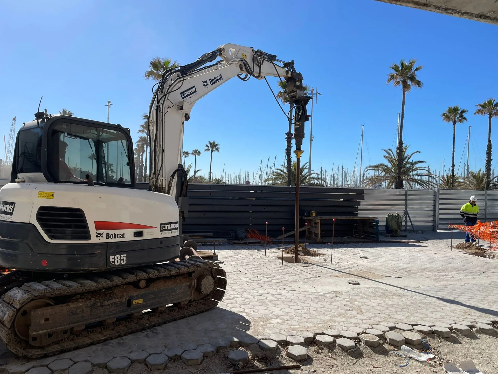
Helical pile installation with excavator-mounted drive head
Engineering Guide

Helical Piles & Helical Piling: A Complete Engineering Guide

How helical piles work, how they are designed, and what load they carry. Includes a KT table for shaft diameters Ø60.3 to Ø323.9, a capacity table by pile size, and four project cases.

What Are They History Components Design Capacity Installation Projects Limitations Cost FAQ
Foundation Technology

What are helical piles?

A helical pile is a steel shaft with one or more helical bearing plates welded near the tip. Rotated into the ground, the helix pulls the pile downward like a wood screw into timber. The pile is driven until it reaches a soil layer that carries the design load. The torque needed to turn it gives a direct measurement of capacity at every depth.

The helix generates both compression capacity (downward) and tension capacity (uplift). This separates helical piles from driven and bored piles. Typical uses include solar racking, building foundations, transmission masts, sound barriers, and underpinning.

No excavation, no spoil, no concrete cure. The pile carries load the moment installation stops.

Paalupiste manufactures two ranges in Finland: PRO for commercial, infrastructure, and solar projects up to about 1,000 kN characteristic capacity, and HELIX for residential and lighter structures that install with a handheld drill or compact excavator. Both are EN 1090 CE certified and designed to Eurocode 7 (EN 1997-1).

Terminology: helical pile = screw pile

Helical pile is the North American term. Screw pile is the European, UK, and Australian term. You will also see helical screw pile, helical anchor, and screw anchor. Same product. This guide uses helical pile and screw pile interchangeably.

Helical pile tip with spiral bearing plate - PRO series by Paalupiste
Origins

A short history of helical piling

The first documented screw pile dates to 1838. Irish engineer Alexander Mitchell patented the system for the Maplin Sands Lighthouse at the mouth of the Thames estuary, where soft sediment would not hold a conventional foundation. The piles were turned into the seabed by hand using capstan bars, and the structure stood for almost 100 years.

Through the 19th century, helical piles supported lighthouses, piers, and bridge footings across the British Empire, the United States, and the Baltic. The Wolf Rock and Coney Island lighthouses still stand on their original 19th-century screw piles.

Hydraulic drive heads replaced manual capstans in the 1980s. A small excavator could now generate tens of kilonewton-metres of torque, and installation rates began to match concrete on full-scale projects.

Paalupiste was founded in 2001 in Porvoo, Finland. The company has manufactured over 700,000 helical piles, delivered across Europe, North America, and the Middle East.

Helical pile installation with excavator-mounted drive head
Anatomy

Components of a helical pile

Five parts: shaft, helix plate, coupling sockets, drive head adapter, and galvanizing.

Shaft

Circular hollow section in steel grade S355J2H. Outer diameter Ø60.3 mm to Ø323.9 mm, wall thickness 2.9 to 12.5 mm. Shafts are joined with internal sleeves to extend beyond a single 6 m segment.

Helix plate

One or more circular steel plates pitched to a 50 mm lead, welded to the shaft near the tip. Plate diameter 150 mm to 500 mm. Plate thickness scales with shaft size: 12 mm up to Ø127, 15 mm for Ø139.7, 20 mm for Ø168.3 and above.

Coupling sockets

Internal sleeves welded to the top of each segment for adding extensions during installation. Standardised bolt patterns across the PRO range.

Drive head adapter

Square or hex coupling at the top that mates with the hydraulic drive head. HELIX piles take a hex bit for a handheld drill.

Galvanizing

Hot-dip galvanizing to EN ISO 1461. Zinc coating typically 70 to 120 microns. In non-aggressive soils the zinc layer lasts 50 to 100 years before wall-thickness loss begins. Steel from SSAB.

Galvanized helical piles in shaft diameters from 60.3 to 219.1 mm, loaded for delivery
Engineering

How helical piles are designed

Two parts: static capacity from soil parameters, and torque-to-capacity correlation that verifies the design during installation.

Torque-to-capacity correlation

The basic relationship:

QT = KT × T

QT is the ultimate axial capacity (kN). T is the installation torque (kNm) measured at end of installation after the helix has reached design depth. KT is a calibration coefficient (m-1) that depends on shaft diameter, soil type, and installation method. Paalupiste KT values come from internal load tests correlated with installations across Northern European soils.

KT values by shaft diameter

Values used in Paalupiste design for cohesionless soils. Site-specific calibration is recommended for heavy loads or soils outside this range.

Shaft diameter KT (m-1) Typical T at design capacity
Ø60.3 mm331.5 to 4 kNm
Ø76.1 mm292 to 6 kNm
Ø88.9 mm243 to 9 kNm
Ø101.6 mm215 to 13 kNm
Ø114.3 mm187 to 18 kNm
Ø139.7 mm1510 to 25 kNm
Ø168.3 mm1215 to 35 kNm
Ø219.1 mm1025 to 60 kNm
Ø273.0 mm and larger835 to 90+ kNm

Values reflect Paalupiste design practice for cohesionless soils with effective friction angles between 32 and 38 degrees. For cohesive clays, fills, and layered profiles, contact our engineering team for project-specific calibration.

Static capacity from soil parameters

For a single-helix pile in cohesionless soil, ultimate compression capacity is bearing capacity of the helix plate plus shaft friction over the embedded length. Typical formulation in EU practice is Vesic-Meyerhof with corrections for plate aspect ratio and depth-to-diameter ratio.

Required soil parameters: effective friction angle (φ'), effective cohesion (c'), undrained shear strength (cu) for clays, effective unit weight, and groundwater conditions. CPT data gives a continuous profile of relative density and undrained strength against depth. CPTU is rarely needed for helical piles unless settlement governs.

Eurocode 7 design approach

Paalupiste designs to EN 1997-1 and the relevant National Annex. UK uses Design Approach 1 (DA1, combinations 1 and 2). Continental EU mostly uses DA2. The characteristic resistance Rk is divided by a model factor γR and a correlation factor ξ3 or ξ4, giving design resistance Rd.

For UK helical piles with installation-torque verification, ξ3 is typically 1.4 when each pile is torque-verified individually. Combined factor of safety from characteristic to design capacity is usually 1.8 to 2.4.

Lateral capacity is evaluated with p-y curves for the relevant soil layers. For most building and solar applications, lateral is governed by serviceability deflection limits, not ultimate failure.

"KT depends on shaft size, soil type, and installation method. We publish ours so you can check the maths."

Tero Paunonen, Paalupiste Oy
Load Capacity

Helical pile load capacity by size

Typical characteristic compression capacity (Rk) for PRO and HELIX piles in medium-dense to dense cohesionless soil. For early-stage sizing only. Actual capacity depends on soil profile, helix configuration, embedded length, and group or lateral effects.

Pile Wall Helix Rk typical Application
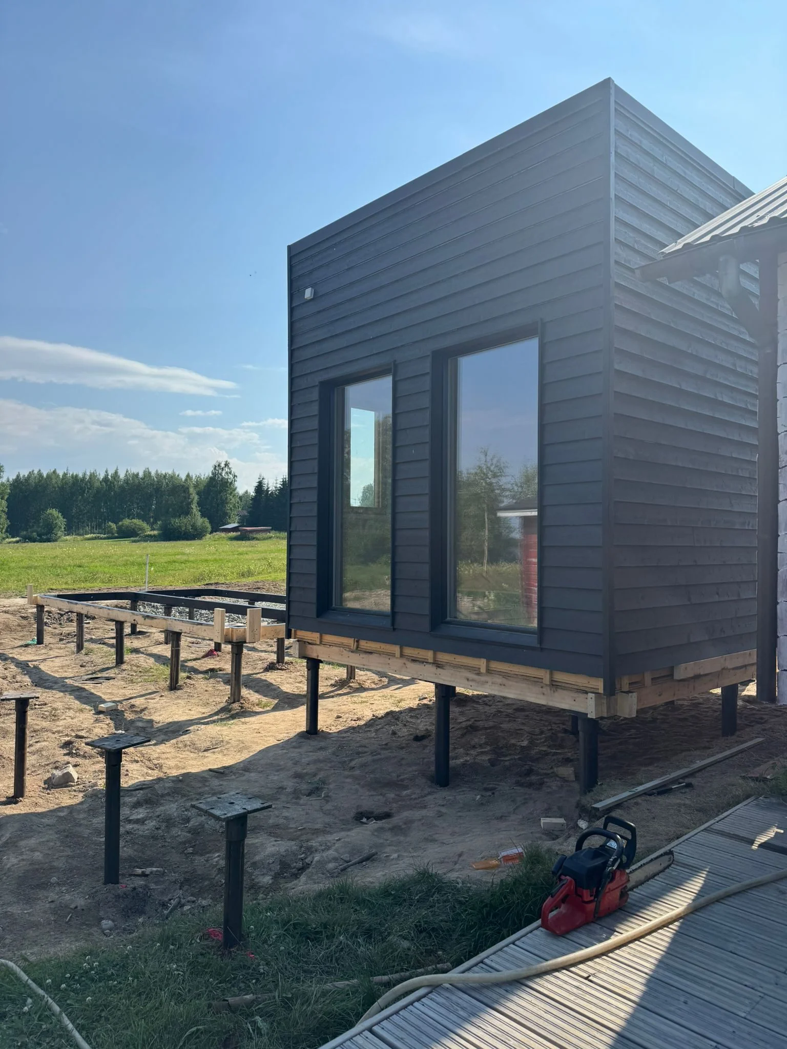
HELIX Ø60.32.9 mmØ150 to 20010 to 30 kNTerraces, sheds, decking, small extensions
PRO Ø60.35.0 mmØ200 to 25030 to 80 kNCabins, light buildings, sound barriers
PRO Ø76.15.0 to 6.3 mmØ200 to 30050 to 150 kNResidential foundations, solar trackers
PRO Ø88.96.3 mmØ250 to 400100 to 250 kNHouses, solar farms, signage masts
PRO Ø114.36.3 mmØ300 to 500200 to 500 kNCommercial buildings, BESS platforms, halls
PRO Ø139.76 mmØ400 to 500300 to 700 kNIndustrial, peat foundations, deep piles
PRO Ø168.38 mmØ400 to 500400 to 900 kNHeavy structures, transmission masts
PRO Ø219.18 to 12 mmØ500600 to 1,200 kNBridge approaches, large infrastructure
PRO Ø273 to 323.910 to 12.5 mmØ5001,000+ kNCustom heavy structures, 110 kV masts

HELIX is single-helix, handheld drill or compact excavator. PRO is excavator-mounted hydraulic drive head, from residential up to heavy infrastructure. Multi-helix configurations increase capacity per pile and reduce embedment in layered soils, especially for solar.

Tension (uplift) capacity is typically 80 to 95 % of compression for double-helix piles. Lateral capacity is governed by serviceability deflection, not ultimate shaft failure, in Ø88.9 and larger.

Advantages

Why professionals choose helical pile foundations

Six measurable advantages that change your project economics. Every claim backed by real site data from thousands of installations across Europe.

50-70%

Faster installation

No excavation, no formwork, no concrete curing. Helical piles screw in and carry load immediately. Your build starts the same day.

Up to 50%

Lower total cost

Eliminate frost insulation, drainage, and multi-phase earthworks. Fewer work steps, fewer invoices, faster project delivery.

about 80%

Less CO₂ than concrete

Zero concrete eliminates the largest carbon source in foundation work. 100% steel, 100% removable, 100% recyclable.

Install year-round, any season - no curing required
No vibration, no noise - safe near existing structures
10 to 1,000+ kN load capacity range
Need helical pile foundations for your project?
Installation

How helical piles are installed

Every pile produces a real-time torque trace that confirms capacity at depth. No equivalent measurement exists for a poured concrete footing.

Pre-installation

Geotechnical investigation gives the soil profile and parameters. CPT sounds at design locations are usually enough. The pile schedule sets shaft diameter, helix configuration, embedded length, and target torque per pile. Piles ship in 6 m segments with joining sleeves pre-welded.

Drive head equipment

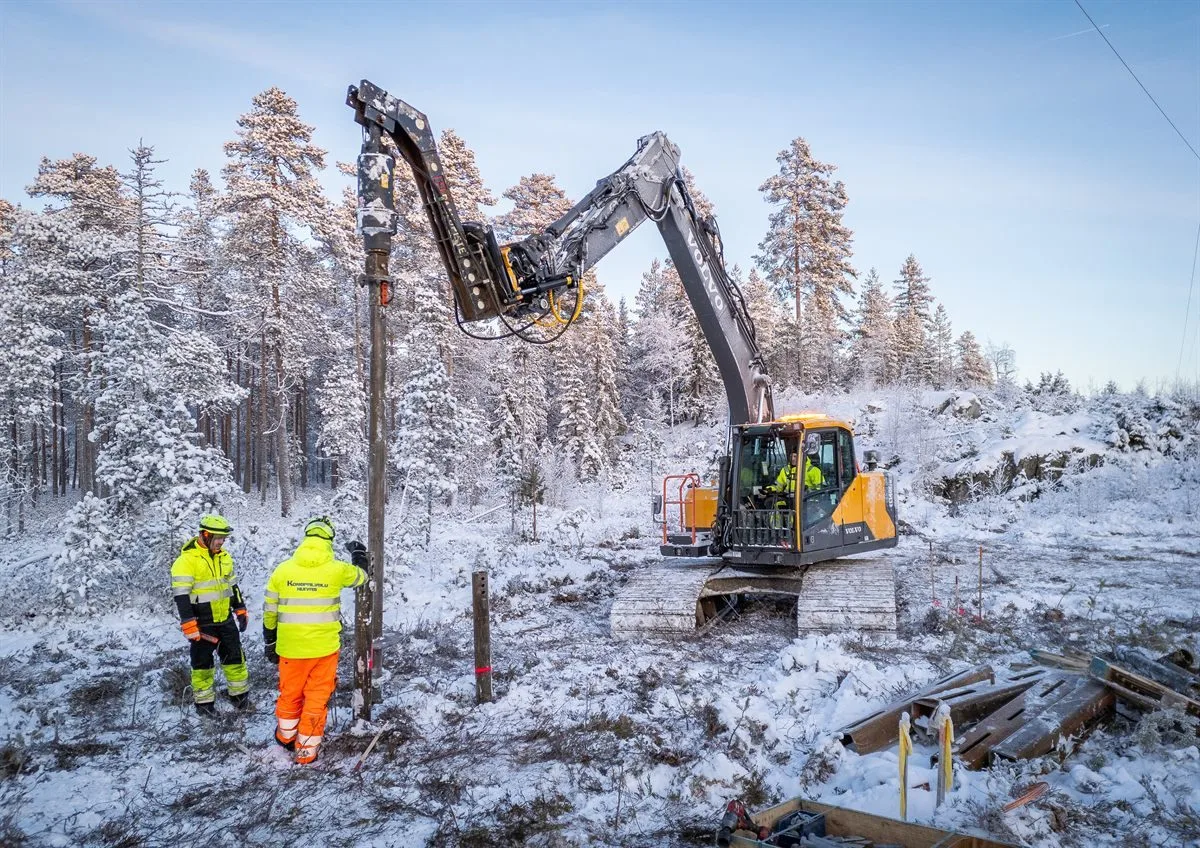
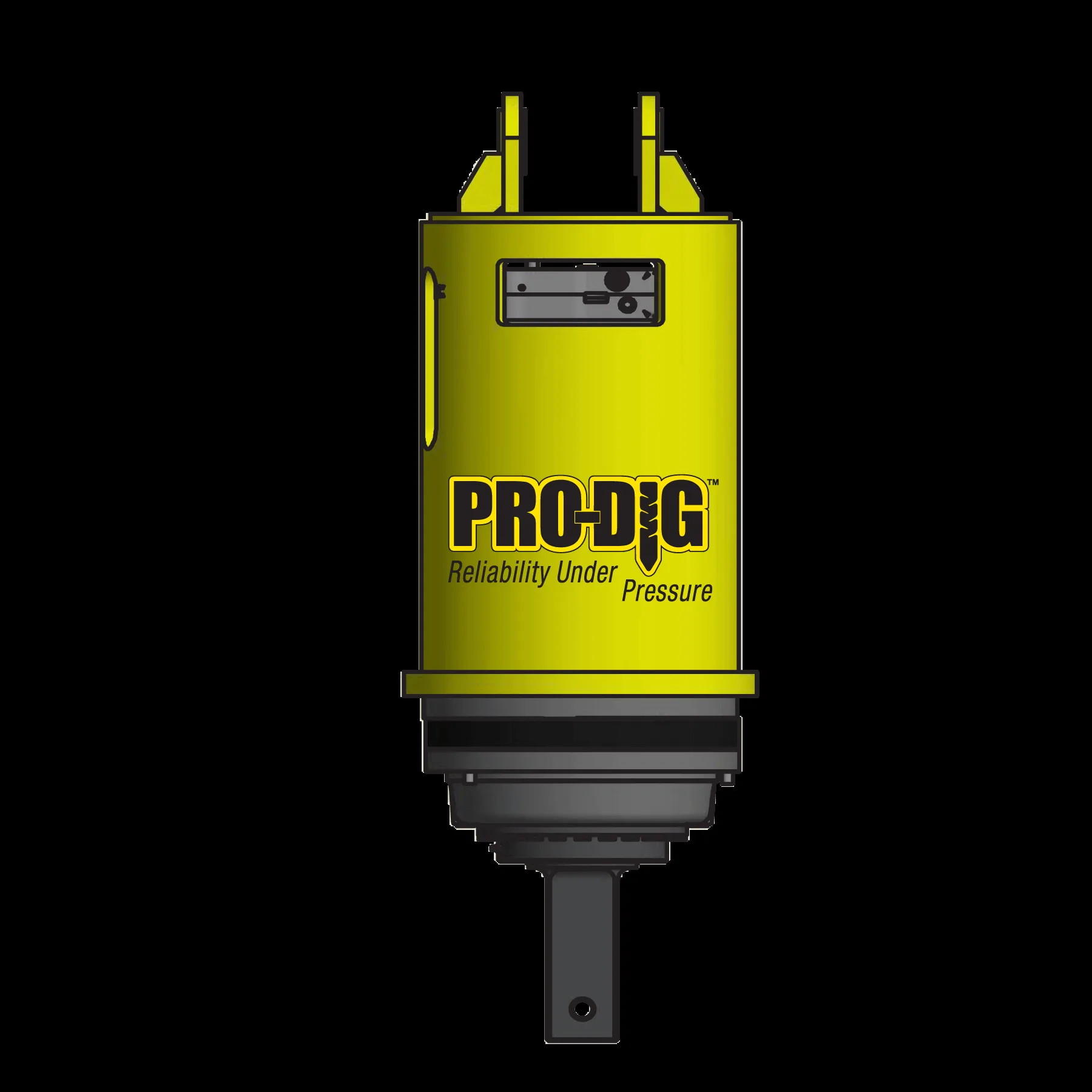
PRO piles up to Ø88.9 install with 5 to 20 kNm drive heads on 5 to 14 tonne excavators. Heavy piles up to Ø323.9 need up to 90 kNm drive heads on 20+ tonne excavators. Digga PD12, PD25, and HyperTorq+ drive heads are standard, all with calibrated torque sensors and data logging. HELIX piles install with an 18 V brushless drill.

Torque monitoring and verification

The drive head logs torque against depth in real time. The operator turns the pile until end-of-installation torque reaches the design value (QT = KT × T). The torque log is the per-pile certificate. Under EN 1997-1 with per-pile verification, separate proof load tests are usually not required.

Installation rates

Rates depend on pile size, embedment, and soil. A two-operator team with one excavator-mounted drive head installs 30 to 50 PRO Ø88.9 piles per day in homogeneous sand. 20 to 30 per day in firm cohesive soils. Peak observed rate is 65 per day in favourable ground. Solar farms with multiple drive heads in parallel: 200 to 400 per day per crew.

Handover documentation

Each pile gets a report: date, time, GPS, torque, depth, operator. Consolidated reports meet EN 1997-1 verification requirements for building control submission.

Helical pile installation with hydraulic drive head
Project Cases

Real-world helical piling projects

Four projects, four different load types and soil profiles.

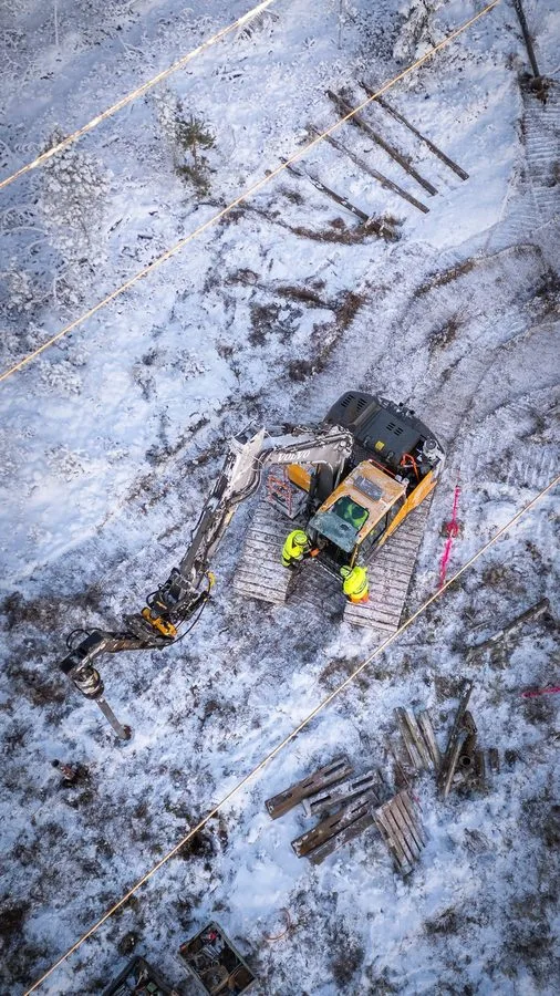
110 kV transmission mast on helical pile foundation

110 kV transmission line, Keuruu, Finland

ELTEL Networks · 2025

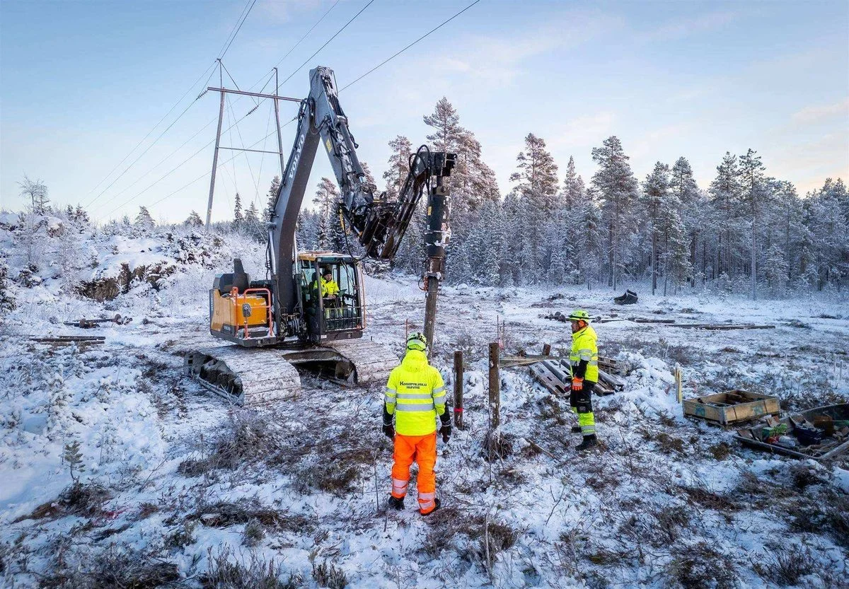
110 kV line between Petajavesi and Haapamaki across mixed forest and bog where concrete delivery was impractical. One Ø220 mm pile or three Ø170 mm piles per mast leg, plus four guy-wire anchors per mast.

Why helical piles: No concrete logistics, completion before winter freeze, removable if the line is decommissioned.

Hallanvahti industrial solar farm on helical piles

Hallanvahti 129 MW solar park, Joroinen, Finland

Eltel Networks · Helicasol · Load-tested for BBA

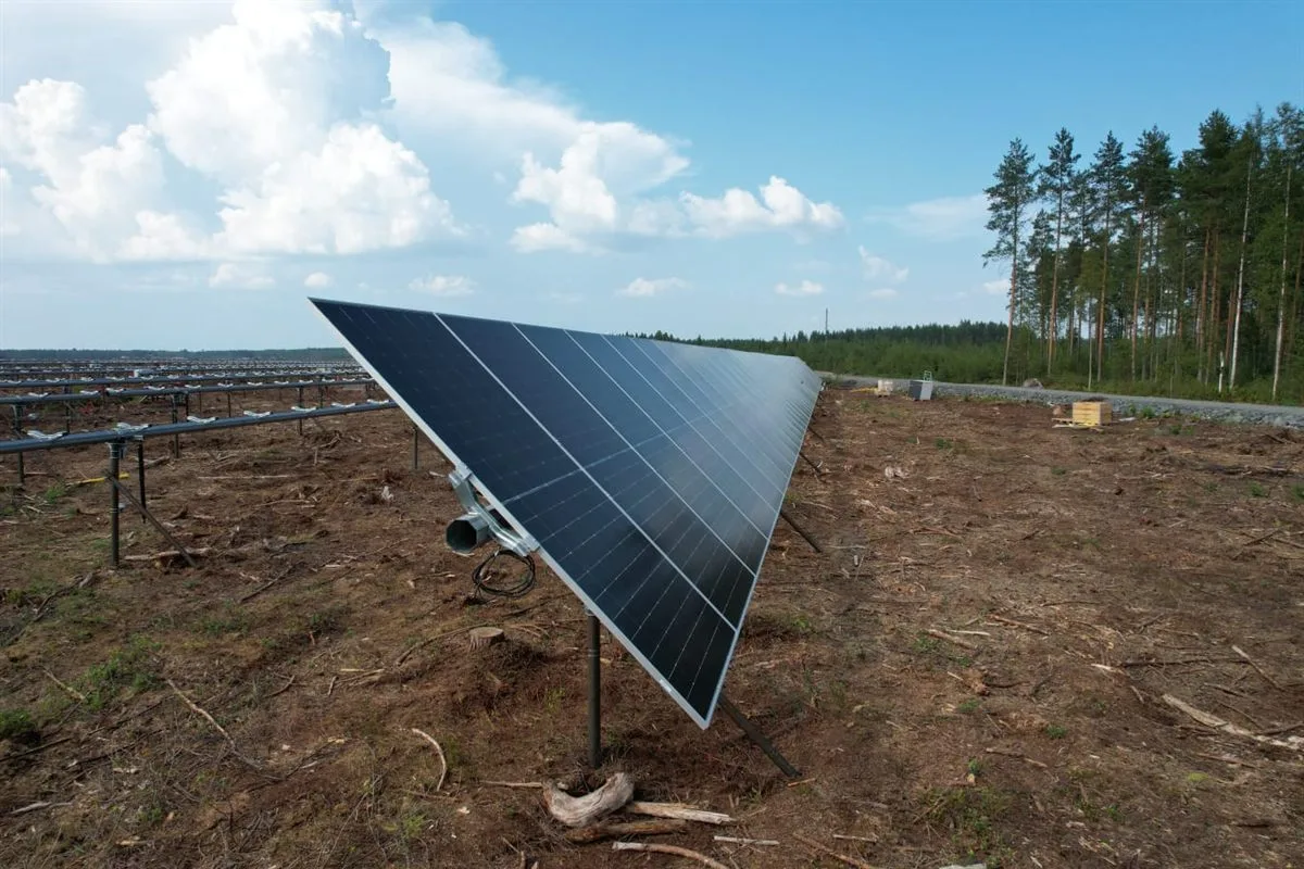
129 MW solar park supplied through Helicasol, Paalupiste's solar subsidiary. The site ran a full load-test programme as part of the BBA certification dossier. Site-specific design reduced the pile count by adapting row by row to the local soil profile.

Why helical piles: Year-round installation, no concrete logistics, removable at end of lease.

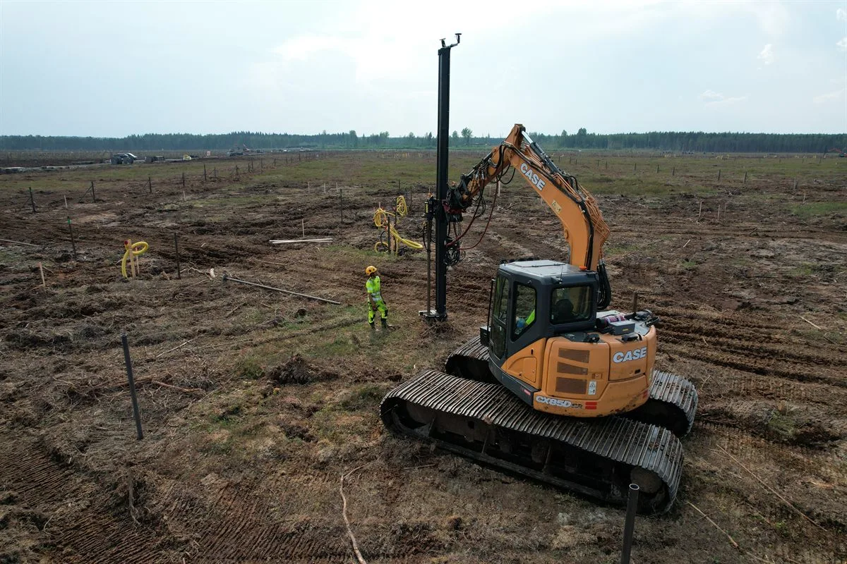
Large-scale helical pile installation, USA berry farm

Berry harvesting infrastructure, USA

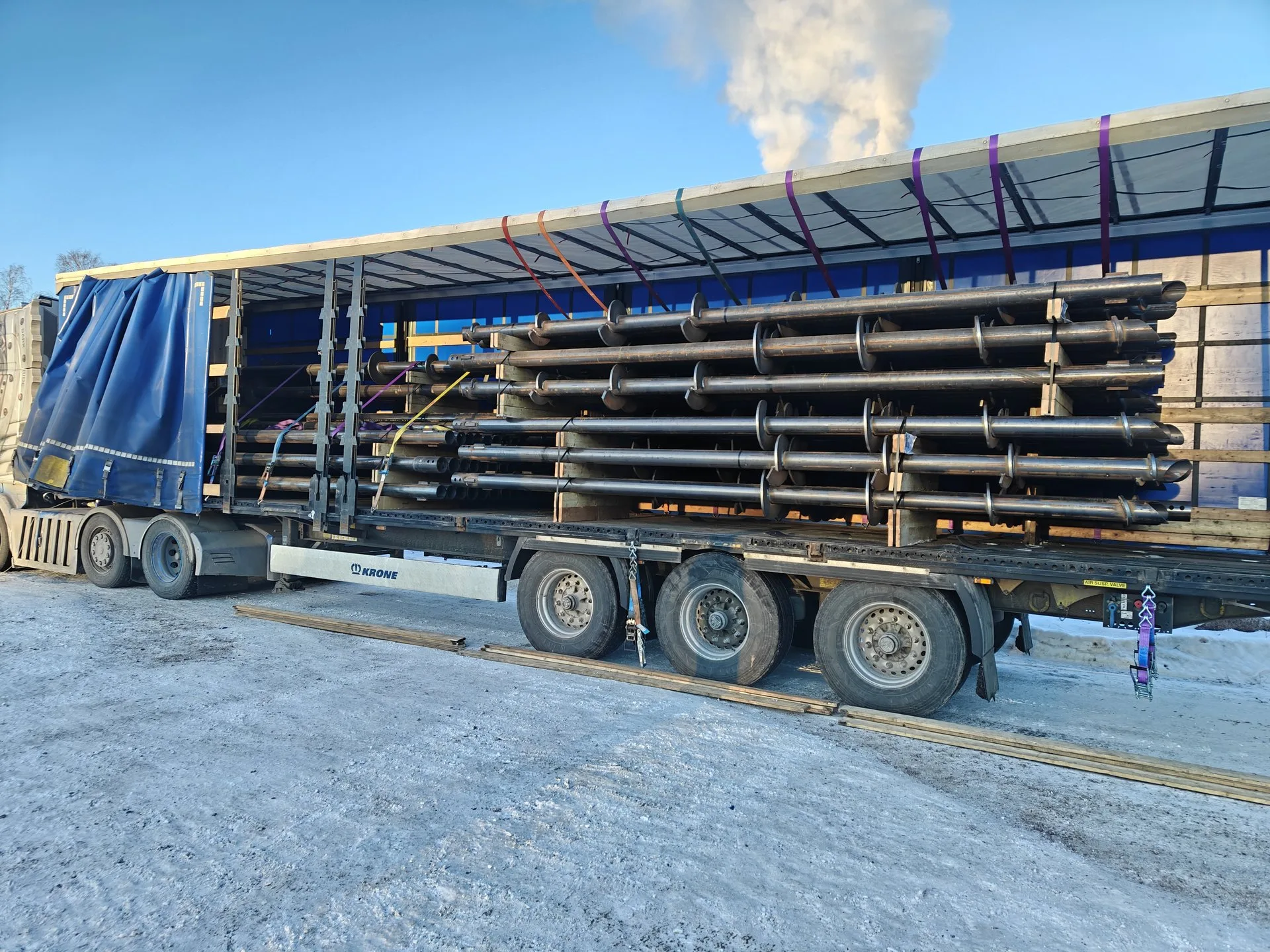
GEGE machinebouw bv · 2 500 piles · 2024

2 500 piles for a US berry-harvesting trellis, delivered in four shipments between May and June 2024. The piles carry an overhead conveyor along the rows of fruit.

Why helical piles: Repeatable installation across thousands of locations, immediate load-bearing, removable at end of crop cycle.

Underpinning project with helical piles

Cinema and restaurant underpinning, Basrah, Iraq

Basrah Mas Company · Soft alluvial soil

Cinema and restaurant complex near Basrah on soft alluvial soil where the original foundations had settled. Helical piles installed adjacent to the building to underpin the structure, with no vibration and no excavation under the existing footing.

Why helical piles: No vibration next to a live structure, full material traceability, performance in soft cohesive soils.

Other projects: 100+ residential foundations across Europe, sound barriers along major rail and motorway corridors, marina platforms, bridge approaches, and several hundred megawatts of solar. Project data available on request.

Where to be Careful

Limitations and site considerations

Where helical piles do not work, where they are difficult, and where they are often wrongly assumed not to work.

Hard limitations

Shallow solid rock. If competent bedrock is less than 1 m below ground, the helix refuses before reaching design embedment. Rock-socketed micropiles or driven piles are the alternative.

Aggressive corrosive soils without mitigation. Low pH, high sulphate, high chloride, or high resistivity can accelerate corrosion beyond standard galvanizing. Designable around with thicker walls, sacrificial wall allowance, or cathodic protection, but soil chemistry must be tested first.

Difficult but manageable

Boulder fill or large rock obstructions. Large rocks in the upper layers stall the pile. May need relocation by a metre or two, pre-augering, or a larger drive head. Adds time and cost but rarely a deal-breaker.

Variable soil profiles. Stratigraphy that changes across the footprint needs pile-by-pile adjustment. Torque verification handles this case directly: each pile is individually verified to capacity.

Often wrongly assumed as a limitation

Peat and very soft soils. Not a hard limit. The design shifts to a longer pile with shaft friction in the underlying competent layer, often with multiple helices for extra bearing. Northern European infrastructure on peat up to 9 m deep is routine.

Cold and frost. Installation runs year-round. Frost heave is resisted by embedment below frost depth, as for any deep foundation.

Helical pile capacity engineering
Standards

Helical pile certifications and design standards

Standards Paalupiste piles are manufactured, designed, and documented to.

EN 1090 (CE marking)

Structural steel under EN 1090-1 factory production control. CE marked to the EU Construction Products Regulation. Audited by Bureau Veritas.

ISO 9001 (quality)

Quality management covering design, manufacturing, traceability, and corrective action. Each pile has a heat number and lot ID traceable to the mill certificate.

ISO 14001 (environment)

Environmental management with documented carbon, waste, and reusable content. Steel from SSAB.

EN ISO 1461 (galvanizing)

Hot-dip galvanizing. Coating 70 to 120 microns. 50 to 100 year design life in non-aggressive soils.

EN 1997-1 (Eurocode 7)

Geotechnical design to the European code. DA1 in the UK, DA2 in most continental jurisdictions, national annexes applied as required.

Third-party inspection

Bureau Veritas inspection available for export markets and projects requiring independent verification of materials, welding, and dimensions.

Cost

What drives the cost of a helical pile foundation

Five factors that drive pricing.

1. Ground conditions

Soft soils need longer piles. Dense soils need bigger drive heads. Layered profiles need design optimisation. CPT data lets us size the pile economically. Most cost surprises come from sites where ground investigation was skipped.

2. Pile size and helix configuration

Steel cost scales with cross-section and length. Ø168.3 uses roughly 3x the steel of Ø88.9 at the same length. Multi-helix piles cost more per pile but can reduce total count enough to lower the overall price.

3. Quantity

Volume discounts on steel, galvanizing, and crew mobilisation are significant. A 50-pile residential project has a higher unit cost than a 5 000-pile solar farm at the same spec.

4. Site distance and access

Mobilising a drive head and crew to a remote site adds a fixed cost. Restricted access (urban infill, sloping ground, water crossings) needs smaller or specialised machinery, which raises the per-pile rate.

5. Working space

A clear, level site lets the drive head move pile-to-pile in minutes. A constrained, sloping, or vegetated site multiplies cycle time. For repeat-pattern projects like solar, this is the single biggest driver of installation cost.

Project estimate

The helical pile calculator gives early-stage sizing for cohesionless soils. For a project-specific quote, contact us.

Local Delivery

Helical piles in your region

Paalupiste delivers across Europe through local partners who handle supply, engineering, and installation in their own market. In the United Kingdom, projects are run by UKHelix, Paalupiste's exclusive UK partner: see helical piles in the UK. In Belgium, Dutch and French-speaking customers are served by Paalupiste Belgium.

Frequently Asked Questions

Helical pile FAQ

Helical piles are steel foundation elements with one or more helical (spiral-shaped) bearing plates welded to a central shaft. They are screwed directly into the ground using an excavator-mounted drive head or a handheld drill, requiring no excavation or concrete. The helical plates provide both compression and tension capacity in a wide range of soil conditions.
Yes. Helical piles and screw piles are the same product. "Helical pile" is the term most commonly used in the United States, while "screw pile" is the standard term in Europe, the UK, and Australia. Other synonyms include helical screw piles, helical anchors, and screw anchors. Regardless of the name, the technology is identical: a steel shaft with helical bearing plates screwed into the ground.
Helical piles are installed by rotating them into the ground using torque. For heavy-duty PRO piles, an excavator-mounted hydraulic drive head provides the torque. For lighter HELIX piles, a handheld electric or hydraulic drill is sufficient. The pile is simply screwed into the soil until it reaches the required depth and torque, which confirms load capacity. No drilling, no excavation, and no concrete are needed.
Helical piles support loads from 10 kN to over 1,000 kN depending on pile diameter, helix size, shaft length, and soil conditions. They handle both compression loads (downward) and tension loads (uplift), making them suitable for everything from garden sheds to solar farms and industrial buildings. Each pile's capacity is verified in real time through torque-to-capacity correlation during installation.
Yes. Helical piles are fully removable by reversing the rotation. This makes them ideal for temporary structures, leased land, and projects where the site must be restored to its original condition. Removed piles can be inspected, re-galvanized if needed, and reused on another project. This is a significant advantage over concrete foundations, which require demolition to remove.
Paalupiste helical piles are manufactured under EN 1090 CE certification for structural steel. The company holds ISO 9001 (quality management) and ISO 14001 (environmental management) certifications. All piles are hot-dip galvanized per EN ISO 1461 and designed according to Eurocode (EN 1997). Steel is sourced from SSAB, one of the world's lowest-carbon steel producers. Full per-pile installation documentation and traceability are standard.
In non-aggressive soils, a hot-dip galvanized helical pile has a design life of 50 to 100 years before any wall-thickness loss begins, based on EN ISO 14713 zinc consumption rates. In soils with aggressive chemistry (low pH, high sulphate, high chloride), design life is reduced and a thicker zinc coating, sacrificial wall allowance, or cathodic protection is specified. Soil chemistry should be tested before specification for projects exceeding 10 years of intended service.
Yes. Helical piles install year-round in freezing conditions. No concrete cure window means no temperature-dependent waiting period. The drive head pushes the helix below the frost line in a single operation, and the pile carries load immediately. Most of our Finnish residential projects install in winter, when the ground is more stable for excavator traffic.
Helical piles are one of the cleanest underpinning methods available. They install with no vibration, no excavation under the existing footing, and no spoil to remove from site. The pile is driven adjacent to the structure and a load-transfer bracket connects it to the original footing. Working access of around 2 m next to the building wall is typically sufficient. The Basrah cinema underpinning project on this page is a representative example.
The drive head logs torque continuously as the pile advances. At final embedment, the operator records the end-of-installation torque T (in kNm). Ultimate axial capacity is calculated as QT = KT × T, where KT is a calibration coefficient that depends on shaft diameter and soil type. For example, a Ø88.9 mm PRO pile with KT of 24 m-1 reaching 8 kNm of installation torque has an ultimate capacity of 192 kN. The recorded torque trace is the per-pile certificate of compliance.
Most residential helical piles are 2 to 5 m deep, reaching the first competent bearing layer below the frost line. Solar farm piles are typically 3 to 6 m. Heavy infrastructure piles (transmission masts, bridge approaches, deep soft-soil profiles) can reach 16 to 22 m using extension segments. Paalupiste piles are supplied in 6 m maximum single-segment lengths and joined with internal sleeves to reach any target depth.
Ready to discuss your helical pile project?